


PERLE PSI-MOS-RS485W2/FO 850 T Serial to Fiber Converter
RS485 2-wire over Fiber - 2-wire RS485 to Redundant Fiber
 Eigenschappen
 Beschrijving
 Verdere informatie
 Vergelijkbare producten
 Print deze pagina
 Prijsaanvraag
 Display mijn notities
 PDF
PDF
 Eigenschappen
 Beschrijving
 Verdere informatie
 PDF
PDF
- Two ST type fiber connectors
- Extend serial data up to 2.6 miles
- Immune to EMI, RFI and transient surges
- Point-to-point or star configuration
- Terminal Block for 2-wire RS485 Connections
For applications where redundancy is required, the PSI-MOS-RS485W2/FO 850 T can be used to transmit data from RS485 2-wire devices out over two fiber optic cables. By transmitting serial data over optical fiber, these serial to fiber converters provide an economical path to extend the reach of RS485 devices. The serial data input is transmitted out both fiber ports to different locations or back-up systems.
All popular protocols with 10/11-bit UART data format and NRZ data coding are supported, such as:
Expandable Serial to Fiber Network infrastructures
Up to ten (10) Serial to Fiber Converters can be grouped together using the TBUS DIN Rail bus system for voltage and data. This allows the serial converter to operate in additional network topology environments:
Long Distance Serial Data Transmission over Fiber
With the FO 850 T Serial to Fiber Converter you can extend your serial data transmission up to 4.2km (2.6 miles). Therefore, any two pieces of asynchronous serial equipment, located miles apart, can communicate at half duplex over fiber optic cable at rates up to 500 kbps.
EMI, RFI and Transient Surge Immunity
Another advantage of the FO 850 T fiber optic transmission system is the electrically isolated connection of devices. Electromagnetic interference (EMI) is a common phenomenon in typical environments like industrial plants, warehouses and factory floors. This interference can cause corruption of data over RS485 or copper-based Ethernet links. Data transmitted over fiber optic cable however is completely immune to this type of noise, thus preventing the negative effects of voltage equalization currents and electromagnetic interference on the data cables. A Serial to Fiber Media Converter therefore enables you to inter-connect your serial devices over fiber ensuring optimal data transmission, increased availability of the system, and improved network design flexibility for point-to-point connections and star structures.
Flexible Fiber Optic Connections
The FO 850 T operates at 850 nm wavelength, using a separate LED emitter and photo-detector on ST type connectors. Almost any multimode glass fiber size can be used including 50/125 m, 62.5/125 m, and 200/230 m.
Power Budget Considerations
Calculating the power budget is critically important with planning the fiber optic link. The optical power budget is the amount of light required to transmit data successfully over distance through a fiber-optic connection. The amount of light energy available within the setup will dictate the length of the fiber optic cable run between serial media converters within the network. Optical power budgets are critical to help businesses avoid signal distortion. To learn how to calculate optical power budget read our technical note. Transmit and receive dBm can be found in the Hardware specifications.
High Quality Features and Support
The FO 850 E are also equipped with comprehensive diagnostic functions to increase system availability, simplify start-up and permanently monitor the optical transmission quality. The integrated optical diagnostics allow permanent monitoring of the FO paths during installation and operation. The floating switch contact is activated when the signal level on the fiber optic paths reaches a critical level. This early alarm generation enables critical system states to be detected before they result in failure. These cost and time saving features, along with free worldwide technical support, make the FO 850 T serial to fiber converter the smart choice for IT professionals.
All popular protocols with 10/11-bit UART data format and NRZ data coding are supported, such as:
- Modbus ASCII / MODBUS RTU
- SUCONET K
- S-BUS
- DH-485, and more
Expandable Serial to Fiber Network infrastructures
Up to ten (10) Serial to Fiber Converters can be grouped together using the TBUS DIN Rail bus system for voltage and data. This allows the serial converter to operate in additional network topology environments:
- as a star coupler, taking the serial data input signal and distributing it to up to 20 Fiber optic output ports
- linear structure can be used to network several RS485 devices
- linear and star structures can be cascaded to create complex tree structures
Long Distance Serial Data Transmission over Fiber
With the FO 850 T Serial to Fiber Converter you can extend your serial data transmission up to 4.2km (2.6 miles). Therefore, any two pieces of asynchronous serial equipment, located miles apart, can communicate at half duplex over fiber optic cable at rates up to 500 kbps.
EMI, RFI and Transient Surge Immunity
Another advantage of the FO 850 T fiber optic transmission system is the electrically isolated connection of devices. Electromagnetic interference (EMI) is a common phenomenon in typical environments like industrial plants, warehouses and factory floors. This interference can cause corruption of data over RS485 or copper-based Ethernet links. Data transmitted over fiber optic cable however is completely immune to this type of noise, thus preventing the negative effects of voltage equalization currents and electromagnetic interference on the data cables. A Serial to Fiber Media Converter therefore enables you to inter-connect your serial devices over fiber ensuring optimal data transmission, increased availability of the system, and improved network design flexibility for point-to-point connections and star structures.
Flexible Fiber Optic Connections
The FO 850 T operates at 850 nm wavelength, using a separate LED emitter and photo-detector on ST type connectors. Almost any multimode glass fiber size can be used including 50/125 m, 62.5/125 m, and 200/230 m.
Power Budget Considerations
Calculating the power budget is critically important with planning the fiber optic link. The optical power budget is the amount of light required to transmit data successfully over distance through a fiber-optic connection. The amount of light energy available within the setup will dictate the length of the fiber optic cable run between serial media converters within the network. Optical power budgets are critical to help businesses avoid signal distortion. To learn how to calculate optical power budget read our technical note. Transmit and receive dBm can be found in the Hardware specifications.
High Quality Features and Support
The FO 850 E are also equipped with comprehensive diagnostic functions to increase system availability, simplify start-up and permanently monitor the optical transmission quality. The integrated optical diagnostics allow permanent monitoring of the FO paths during installation and operation. The floating switch contact is activated when the signal level on the fiber optic paths reaches a critical level. This early alarm generation enables critical system states to be detected before they result in failure. These cost and time saving features, along with free worldwide technical support, make the FO 850 T serial to fiber converter the smart choice for IT professionals.
- Supply voltage and data signals routed through via DIN rail connectors
- Connections can be plugged in using a COMBICON screw terminal block
- Automatic data rate detection or fixed data rate setting via DIP switches
- Redundant power supply possible by means of optional system power supply unit
- High-quality electrical isolation between all interfaces (RS-485, fiber optic ports, power supply, DIN rail connector)
- Approved for use in zone 2
- Integrated optical diagnostics for continuous monitoring of fiber optic paths
- Intrinsically safe fiber optic interface (Ex op is) for direct connection to devices in zone 1
- Floating switch contact for leading alarm generation in relation to critical fiber optic paths
- Suitable for data rates up to 500 kbps
| PSI-MOS-RS485W2/FO 850 T Serial to Fiber Media Converter Applications |
|---|
|
| Point-to-point connections between serial devices over fiber |
Configure the point-to-point connection redundantly to increase availability by using two PSI-MOS-RS485W2/FO 850 T Serial to Fiber Converters. Easily convert a data link from a single copper cable out to two fiber optic cables.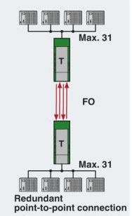 |
| Redundant Star Topology Network |
You can network RS-485 2-wire devices within a star structure. Depending on the number of star lines required, several PSI-MOS-RS485W2/FO 850 T Serial to Fiber Converters are connected to TBUS DIN Rail bus systems for voltage and data. This makes up to 20 fiber optic ports available. Cross-wiring for serial data and the supply voltage is provided automatically by the DIN rail connector.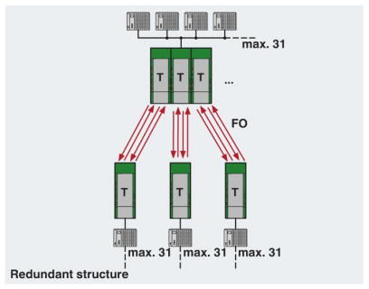 |
| Linear Networks |
The fiber optic linear structure can be used to network several RS-485 2-wire devices. FO 850 E serial to fiber converters are used at the beginning and end of the fiber optic line. FO 850 T serial to fiber converters with two fiber optic ports are used along the line. You can use up to ten PSI-MOS-RS2485/FO devices along the line in a linear structure.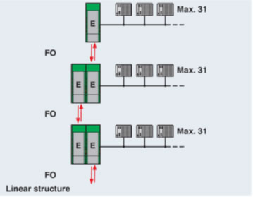 |
| Tree Networks |
Linear and star structures can be cascaded to create complex tree structures, in a redundant configuration. The number of devices that can be cascaded is only limited by the timing response (timeout) of the bus system used due to the bit retiming of the serial to fiber optic converter.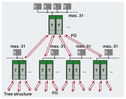 |
| Block Diagram |
 |
PSI-MOS-RS485W2/FO 850 T Technical Specifications
| Ambient conditions | |
|---|---|
| Ambient temperature (operation) | -20 °C ... 60 °C |
| Ambient temperature (storage/transport) | -40 °C ... 85 °C |
| Permissible humidity (operation) | 30 % ... 95 % (non-condensing) |
| Altitude | 5000 m (For restrictions see manufacturer´s declaration) |
| Degree of protection | IP20 |
| Noise immunity | EN 61000-6-2:2005 |
| Standards and Regulations | |
| Electromagnetic compatibility | Conformance with EMC Directive 2014/30/EU |
| Type of test | Vibration resistance in acc. with EN 60068-2-6/IEC 60068-2-6 |
| Test result | 5g, 10-150 Hz, 2.5 h, in XYZ direction |
| Type of test | Shock in acc. with EN 60068-2-27/IEC 60068-2-27 |
| Test result | 15g, 11 ms period, half-sine shock pulse |
| Shock | 15g in all directions in acc. with IEC 60068-2-27 |
| Noise emission | EN 55011 |
| Noise immunity | EN 61000-6-2:2005 |
| Free from substances that could impair the application of coating | according to P-VW 3.10.7 57 65 0 VW-AUDI-Seat central standard |
| Connection in acc. with standard | CUL |
| Standards/regulations | EN 61000-4-2 EN 61000-4-3 EN 61000-4-4 EN 61000-4-5 EN 61000-4-6 |
| Vibration (operation) | In acc. with IEC 60068-2-6: 5g, 150 Hz |
| Conformance | CE-compliant |
| ATEX | II 3 G Ex nA nC IIC T4 Gc X II (2) G [Ex op is Gb] IIC (PTB 06 ATEX 2042 U II (2) D [Ex op is Db] IIIC (PTB 06 ATEX 2042 U) |
| UL, USA/Canada | Class I, Zone 2, AEx nc IIC T5 Class I, zone 2, Ex nC nL IIC T5 X Class I, Div. 2, Groups A, B, C, D |
| Optical interface FO | |
| Number of FO ports | 2 |
| Transmit capacity, minimum | -4 dBm (200/230 µm) -17.6 dBm (50/125 µm) -14 dBm (62,5/125 µm) |
| Minimum receiver sensitivity | -32.5 dBm (50/125 µm) -32.5 dBm (62,5/125 µm) -32.1 dBm (200/230 µm) |
| Overrange receiver | -3 dBm (200/230 µm) |
| Wavelength | 850 nm |
| Transmission length incl. 3 dB system reserve | 2800 m (with F-K 200/230 8 dB/km with quick mounting connector) 4200 m (with F-G 50/125 2.5 dB/km) 3300 m (with F-G 62,5/125 3.0 dB/km) |
| Transmission medium | PCF fiber Multi-mode fiberglass |
| Transmission protocol | Protocol-transparent to the RS-485 interface |
| Connection method | B-FOC (duplex ST®) |
| General | |
| Bit delay | ≤ 1 bit |
| Bit distortion, input | ± 35 % (permitted) |
| Bit distortion, output | < 6.25 % |
| Electrical isolation | VCC // RS-485 |
| Test voltage data interface/power supply | 1.5 kVrms (50 Hz, 1 min.) |
| Electromagnetic compatibility | Conformance with EMC Directive 2014/30/EU |
| Noise emission | EN 55011 |
| Net weight | 210.08 g |
| Housing material | PA 6.6-FR |
| Color | green |
| MTBF | 159 Years (Telcordia standard, 25°C temperature, 21% operating cycle (5 days a week, 8 hours a day)) 24 Years (Telcordia standard, 40°C temperature, 34.25% operating cycle (5 days a week, 12 hours a day)) |
| Conformance | CE-compliant |
| ATEX | II 3 G Ex nA nC IIC T4 Gc X (Please follow the special installation instructions in the documentation!) II (2) G [Ex op is Gb] IIC (PTB 06 ATEX 2042 U) (Please follow the special installation instructions in the documentation!) II (2) D [Ex op is Db] IIIC (PTB 06 ATEX 2042 U) (Please follow the special installation instructions in the documentation!) |
| UL, USA/Canada | Class I, Zone 2, AEx nc IIC T5 Class I, zone 2, Ex nC nL IIC T5 X Class I, Div. 2, Groups A, B, C, D |
| Digital outputs | |
| Output name | Relay output |
| Output description | Alarm output |
| Number of outputs | 1 |
| Maximum switching voltage | 60 V DC 42 V AC |
| Limiting continuous current | 0.46 A |
| Power supply | |
| Nominal supply voltage | 24 V DC (With UL approval) |
| Supply voltage range | 18 V DC ... 30 V DC |
| Max. current consumption | 130 mA |
| Typical current consumption | 120 mA (24 V DC) |
| Connection method | COMBICON plug-in screw terminal block |
| Serial interface | |
| Interface 1 | RS-485 interface, 2-wire |
| Operating mode | Semi-duplex |
| Connection method | Pluggable screw connection |
| File format/coding | UART (11/10 bit switchable; NRZ), slip-tolerant |
| Data direction switching | Automatic control |
| Transmission medium | Copper |
| Transmission length | ≤ 1200 m (depending on the data rate, with shielded, twisted data cable) |
| Termination resistor | 390 Ω 220 Ω 390 Ω (Can be connected) |
| Conductor cross section solid min. | 0.2 mm² |
| Conductor cross section solid max. | 2.5 mm² |
| Conductor cross section flexible min. | 0.2 mm² |
| Conductor cross section flexible max. | 2.5 mm² |
| Conductor cross section AWG min. | 24 |
| Conductor cross section AWG max. | 14 |
| Serial transmission speed | 4.8/ 9.6/ 19.2/ 38.4/ 57.6/ 75/ 93.75/ 115.2/ 136/ 187.5/ 375/ 500 kbps |
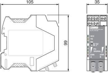
| Dimensions | |
| Width | 35 mm |
| Height | 99 mm |
| Depth | 105 mm |
 | |
| Environmental Product Compliance | |
| China RoHS | Environmentally Friendly Use Period = 50 |
| Reach and RoHS Compliant | Yes |
| Approvals | |
| cUL Listed cULus Listed UL Listed ATEX EAC DNV cUL Recognized cULus Recognized UL Recognized | |
| Commercial data | |
| Packing unit | 1 |
| Weight per piece | 249.0 g |
| Country of origin | Germany |
| Warranty | 1 Year |
| Classifications | |
| eCl@ss 4.0 | 27230207 |
| eCl@ss 4.1 | 27230207 |
| eCl@ss 5.0 | 27230207 |
| eCl@ss 5.1 | 27230207 |
| eCl@ss 6.0 | 27230207 |
| eCl@ss 7.0 | 27230207 |
| eCl@ss 8.0 | 19179290 |
| eCl@ss 9.0 | 19179290 |
| ETIM 2.0 | EC001423 |
| ETIM 3.0 | EC001423 |
| ETIM 4.0 | EC001423 |
| ETIM 5.0 | EC000310 |
| ETIM 6.0 | EC000310 |
| UNSPSC 6.01 | 30211506 |
| UNSPSC 7.0901 | 39121008 |
| UNSPSC 11 | 39121008 |
| UNSPSC 12.01 | 39121008 |
| UNSPSC 13.2 | 43222604 |
 Klanten keken ook naar deze producten